Selecting the right cable gland (cable sealing joint) is an easily overlooked yet critical step in electrical installation. Especially in scenarios such as armoured cable wiring in heavy industry and equipment connection in hazardous areas, a suitable cable gland is the core to ensuring mechanical tightness, environmental sealing and long-term operational reliability. Specializing in industrial-grade cable connectors, Hoonsun Cable Gland offers a full range of armoured, double-clamp and explosion-proof cable glands in brass and stainless steel. This article elaborates on the core principles of cable gland selection, methods for interpreting sizing charts and specific model matching strategies, providing a comprehensive reference for industrial project selection.
More than just securing cables, cable glands perform multiple key functions. Improper selection will directly compromise the operational safety of electrical systems:
• Maintain the ingress protection rating of equipment enclosures and prevent the intrusion of dust and moisture;
• Provide strain relief for cables to avoid damage from pulling and vibration;
• Bond or clamp the armour layer as required to ensure electrical continuity;
• Achieve hermetic isolation against moisture, dust and corrosive media;
Meet flame-retardant and explosion-proof standards in flammable and explosive environments.
An undersized gland will crush and damage cable insulation, while an oversized one will compromise sealing performance and reduce the IP rating. Precise size matching is the key to avoiding these issues.
Before referring to sizing charts, four core factors must be clarified to define the basic scope for selection:
Different armoured cable types correspond to cable glands of different structures. Common types include: unarmoured cable, steel wire armoured (SWA) cable, steel tape armoured cable, and double armoured cable.
The cable outer diameter directly determines the clamping range of the cable gland. Always measure the actual outer diameter of the cable instead of just referring to the nominal size—this is the core basis for selection.
The thread of the cable gland must match that of the enclosure entry hole. Industry universal standards and those supported by Hoonsun include: Metric, PG, NPT, and G (BSPP) threads.
Determine the ingress protection rating, explosion-proof certification and special performance of the cable gland based on environmental requirements:
• General industrial scenarios: IP54 compliance is sufficient;
• Outdoor and washdown scenarios: IP68 high ingress protection rating is required;
• Hazardous areas: compliance with Ex d IIC Gb explosion-proof standard;
• Fire-resistant requirements: compliance with UL94-V0 flame-retardant rating.
Hoonsun has launched a variety of armoured and explosion-proof cable glands adapted to different scenarios, covering IP54 basic protection, IP68 high protection and explosion-proof ratings. The following are the sizing parameters and application scopes of core series, all of which are commonly used models in industrial scenarios.
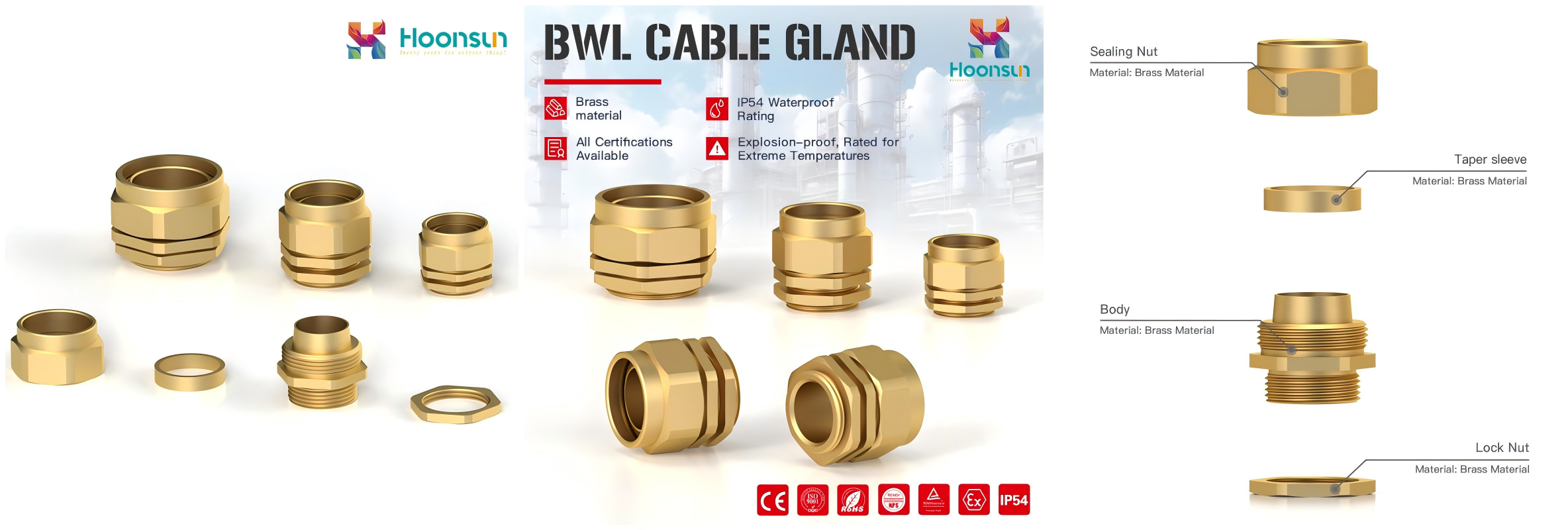
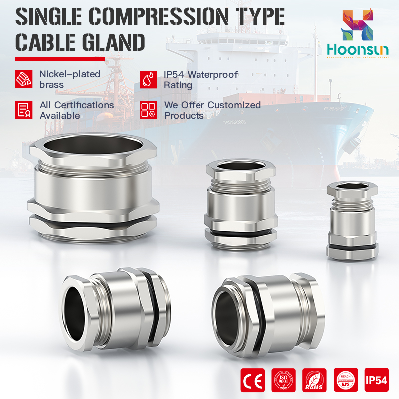
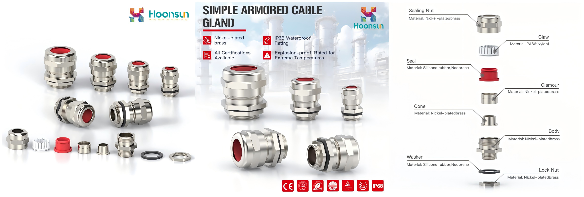
A basic brass cable gland suitable for armoured cable wiring in general industrial scenarios, available in L (large size) and S (small size) models with the following core parameters:
|
Thread Specification |
Cable OD Min (mm) |
Cable OD Max (mm) |
Thread Length GL (mm) |
Joint Length H (mm) |
Spanner Size (mm) |
Product Code |
|
M20×1.5 |
14 |
21.1 |
10 |
17 |
24 |
HX-BWL-20L |
|
M20×1.5 |
11.7 |
16.1 |
10 |
17 |
22/23 |
HX-BWL-20S |
|
M25×1.5 |
20 |
27 |
10 |
23 |
34 |
HX-BWL-25L |
|
M25×1.5 |
19 |
24 |
10 |
23 |
31 |
HX-BWL-25S |
|
M32×1.5 |
26.2 |
33 |
10 |
23 |
40 |
HX-BWL-32L |
|
M32×1.5 |
24 |
30.5 |
10 |
23 |
36 |
HX-BWL-32S |
|
M40×1.5 |
32.5 |
41 |
10 |
25 |
45/48 |
HX-BWL-40L |
|
M50×1.5 |
44.1 |
55.7 |
15 |
32 |
55/63 |
HX-BWL-50L |
|
M63×1.5 |
56 |
68.2 |
15 |
38 |
78 |
HX-BWL-63L |
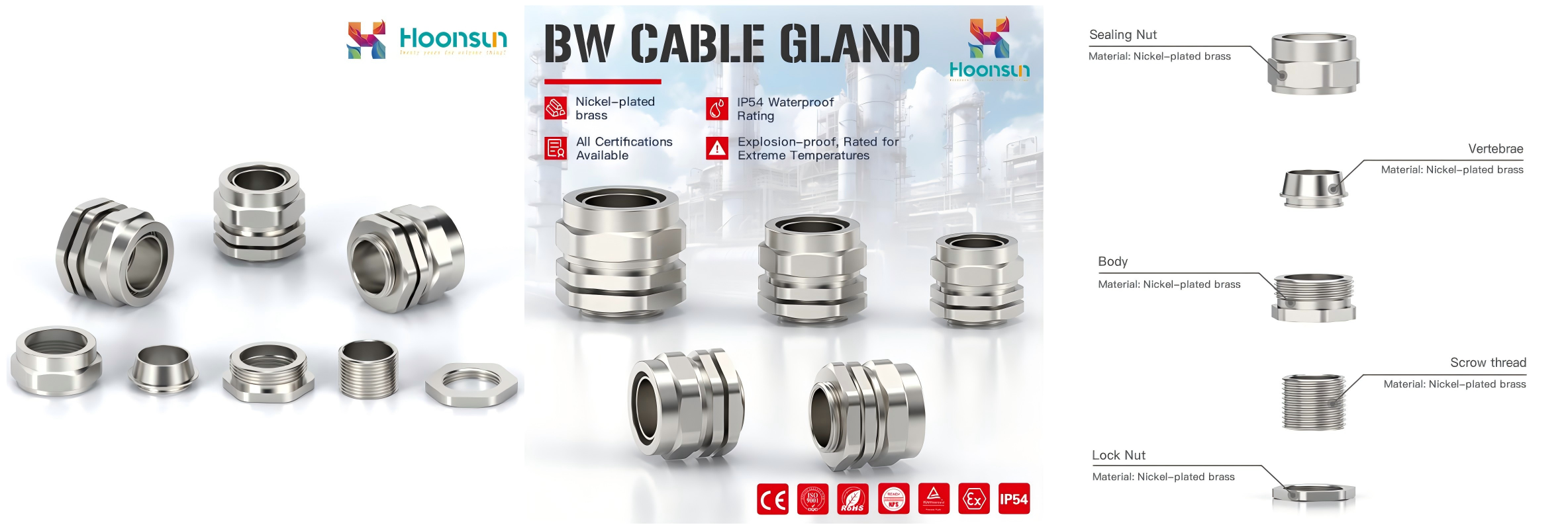
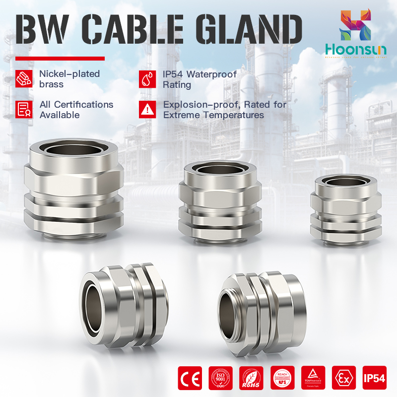
Nickel-plated brass enhances corrosion resistance, making it suitable for industrial scenarios with mild corrosion. The full series is available in models 0 to 6 with the following parameters:
|
Model |
Thread Specification |
Cable OD Min (mm) |
Cable OD Max (mm) |
Thread Length (mm) |
Joint Length (mm) |
Spanner Size (mm) |
Product Code |
|
BW-0 |
M20×1.5 |
12.6 |
16.5 |
10 |
23 |
22 |
HX-BW0 |
|
BW-1 |
M20×1.5 |
15.9 |
19.0 |
10 |
26 |
27/25/24 |
HX-BW1 |
|
BW-2 |
M25×1.5 |
20.6 |
26.5 |
10 |
29 |
35 |
HX-BW2 |
|
BW-3 |
M32×1.5 |
26.5 |
33.0 |
10 |
32 |
40 |
HX-BW3 |
|
BW-4 |
M40×1.5 |
34.9 |
40.5 |
15 |
36 |
50 |
HX-BW4 |
|
BW-5 |
M50×1.5 |
44.5 |
51.0 |
15 |
45 |
64 |
HX-BW5 |
|
BW-6 |
M63×1.5 |
57.0 |
67.0 |
15 |
50 |
82 |
HX-BW6 |
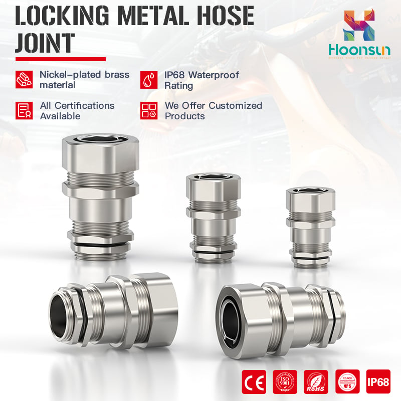
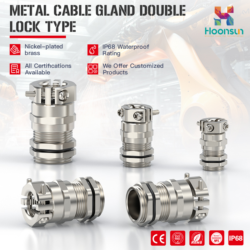
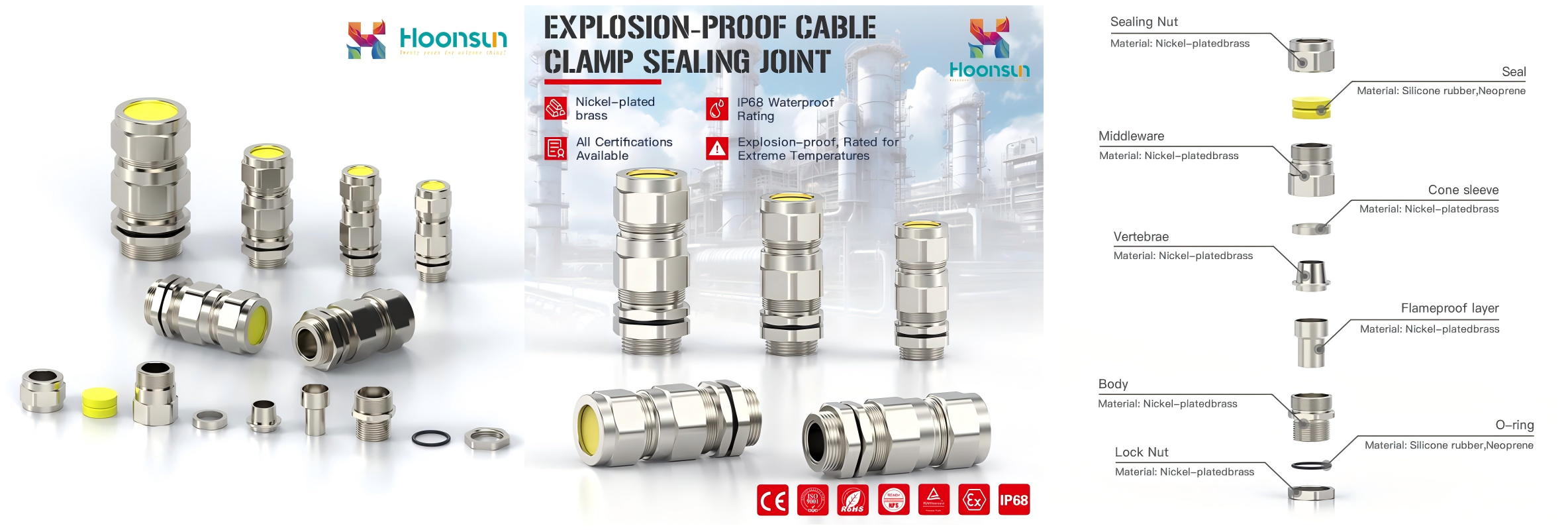
The double compression structure achieves enhanced sealing and mechanical retention with an IP68 ingress protection rating, suitable for harsh scenarios such as outdoor installations, oil and gas stations, marine engineering and high-vibration environments. The core representatives are the EX1 explosion-proof series and the EX3 clamp sealing series.
• EX1 Series Armoured Explosion-Proof Gland: Designed specifically for explosion-proof environments, with differentiated ranges for outer and inner sheath OD and armour layer:
|
Thread Specification |
Outer Sheath OD (mm) |
Inner Sheath OD (mm) |
Armor Range (mm) |
Thread Length GL (mm) |
Joint Length H (mm) |
Product Code |
|
M20×1.5 |
10–14 |
6–10 |
0.9/1.25 |
15 |
30 |
HX-EX1.M20-14 |
|
M20×1.5 |
13–18 |
9–14 |
0.9/1.25 |
15 |
32 |
HX-EX1.M20-18 |
|
M25×1.5 |
17–24 |
13–20 |
1.25/1.6 |
15 |
35 |
HX-EX1.M25 |
|
M32×1.5 |
23–32 |
18–26 |
1.6/2.0 |
15 |
39 |
HX-EX1.M32 |
|
M40×1.5 |
31–38 |
25–32 |
1.6/2.0 |
15 |
43 |
HX-EX1.M40 |
|
M50×1.5 |
37–44 |
31–38 |
1.8/2.5 |
15 |
48 |
HX-EX1.M50 |
|
M63×1.5 |
45–55 |
36–47 |
1.8/2.5 |
15 |
53 |
HX-EX1.M63 |
• EX3 Series Explosion-Proof Cable Clamp Sealing Joint: Supports both Metric and inch threads, suitable for various explosion-proof scenarios:
|
Metric Thread |
Inch Thread |
Cable OD Range (mm) |
Thread Length (mm) |
Joint Length (mm) |
Product Code |
|
M16×1.5 |
G3/8 |
7–15 |
15 |
53 |
HX-EX3.M16-15 |
|
M20×1.5 |
G1/2 |
7–15 |
15 |
53 |
HX-EX3.M20-15 |
|
M25×1.5 |
G3/4 |
11–20 |
15 |
53 |
HX-EX3.M25-20 |
|
M32×1.5 |
G1 |
14–25 |
17 |
60 |
HX-EX3.M32-25 |
|
M40×1.5 |
G1-1/4 |
19–33 |
17 |
70 |
HX-EX3.M40-33 |
|
M50×1.5 |
G1-1/2 |
24–41 |
17 |
78 |
HX-EX3.M50-41 |
|
M63×1.5 |
G2 |
30–50 |
17 |
82 |
HX-EX3.M63-50 |
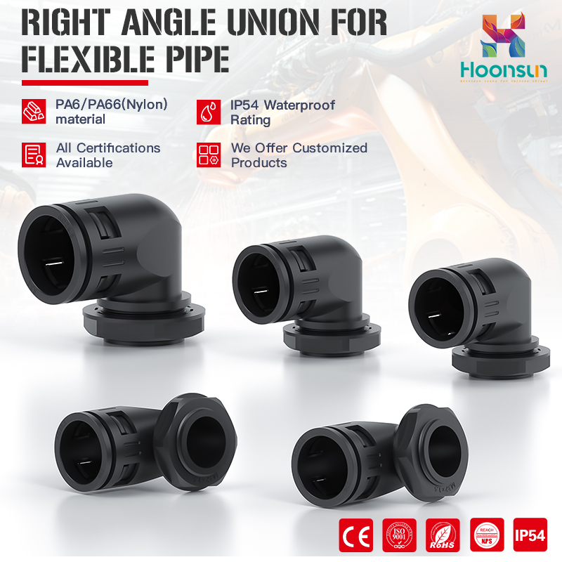
Featuring a simplified structural design, it is suitable for armoured cable wiring in general industrial scenarios with space constraints for installation, with differentiated incoming and outgoing cable OD:
|
Thread Specification |
Incoming Cable OD (mm) |
Outgoing OD (mm) |
Thread Length (mm) |
Joint Length (mm) |
Product Code |
|
M20×1.5 |
14–20.9 |
16 |
10 |
35 |
HX-CW-20L |
|
M25×1.5 |
20–27 |
21.5 |
10 |
55 |
HX-CW-25L |
|
M32×1.5 |
26.2–33 |
27 |
10 |
55 |
HX-CW-32L |
|
M40×1.5 |
32.5–41 |
35 |
11 |
50 |
HX-CW-40L |
|
M50×1.5 |
44.1–53.1 |
45 |
15 |
57 |
HX-CW-50L |
|
M63×1.5 |
50–59.4 |
59 |
15 |
68 |
HX-CW-63L |
Sizing charts are the direct basis for selection. When interpreting, focus on five core columns to avoid selection deviations caused by misreading parameters:
• Thread Specification: Determines the compatibility of the cable gland with the enclosure entry hole and must be an exact match;
• Cable OD Range: The most critical parameter for selection—the measured cable OD must fall within this range;
• Thread Length (GL): Indicates the length of the threaded section of the cable gland screwed into the enclosure, which must be considered in conjunction with the enclosure wall thickness;
• Joint Length (H): The overall compression length of the cable gland, which affects installation space and sealing performance;
• Spanner Size: Specifies the wrench size required for installation to ensure construction convenience.
In the actual selection process, the following mistakes are likely to cause mismatches between cable glands and scenarios and must be avoided:
• Equating the nominal cable size with the actual OD: The nominal size is for reference only, and the measured OD is the only standard;
• Ignoring armour layer thickness: The armour layer increases the overall cable OD and must be considered in selection;
• Confusing Metric and NPT threads: The two thread standards are not interchangeable—confirm the thread type of the enclosure entry hole;
• Overlooking enclosure wall thickness: The thread length must match the wall thickness; an insufficient length will result in ineffective fixation and sealing;
• Selecting a lower ingress protection rating than required: Misusing IP54 cable glands in outdoor, humid and washdown scenarios leads to protection failure;
• Failing to verify hazardous area certification: Using cable glands without Ex d IIC Gb certification in explosion-proof environments poses potential safety hazards.
A cable gland sizing chart is not a simple list of dimensions but a technical selection tool to ensure the safe operation of electrical systems. Its ultimate goals are to achieve: proper mechanical retention, long-term environmental sealing, compliance with industry specifications and regulatory requirements, guaranteed electrical continuity, and safe installation and operation.
When selecting cable glands for industrial and hazardous environments, do not use thread specification as the sole criterion. Instead, comprehensively evaluate the complete set of parameters including cable type, actual OD, application environment, ingress protection rating and explosion-proof certification. For complete technical documentation, explosion-proof certification certificates and professional engineering selection support for the full range of Hoonsun cable glands, please visit the official website: https://www.hoonsuncg.com
 Hot News
2026-07-09
2026-07-06
2026-06-22
2026-06-17
2026-06-15
2026-06-09

Copyright © Zhejiang Hongxiang Connector Co., Ltd. All Rights Reserved - Privacy Policy